Single-Area OSPFv2 Concepts
Module Objective: Explain how single-area OSPF operates in both point-to-point and broadcast multiaccess networks.
| Topic Title | Topic Objective |
| OSPF Features and Characteristics | Describe basic OSPF features and characteristics. |
| OSPF Packets | Describe the OSPF packet types used in single-area OSPF. |
| OSPF Operation | Explain how single-area OSPF operates. |
OSPF Features and Characteristics Introduction to OSPF
- OSPF is a link-state routing protocol that was developed as an alternative for the distance vector Routing Information Protocol (RIP). OSPF has significant advantages over RIP in that it offers faster convergence and scales to much larger network implementations.
- OSPF is a link-state routing protocol that uses the concept of areas. A network administrator can divide the routing domain into distinct areas that help control routing update traffic.
- A link is an interface on a router, a network segment that connects two routers, or a stub network such as an Ethernet LAN that is connected to a single router.
- Information about the state of a link is known as a link-state. All link-state information includes the network prefix, prefix length, and cost.
- This module covers basic, single-area OSPF implementations and configurations.
Components of OSPF
- All routing protocols share similar components. They all use routing protocol messages to exchange route information. The messages help build data structures, which are then processed using a routing algorithm.
- Routers running OSPF exchange messages to convey routing information using five types of packets:
- Hello packet
- Database description packet
- Link-state request packet
- Link-state update packet
- Link-state acknowledgment packet
- These packets are used to discover neighboring routers and also to exchange routing information to maintain accurate information about the network.
OSPF messages are used to create and maintain three OSPF databases, as follows:
| Database | Table | Description |
| Adjacency Database | Neighbor Table |
|
| Link-state Database (LSDB) | Topology Table |
|
| Forwarding Database | Routing Table |
|
- The router builds the topology table using results of calculations based on the Dijkstra shortest-path first (SPF) algorithm. The SPF algorithm is based on the cumulative cost to reach a destination.
- The SPF algorithm creates an SPF tree by placing each router at the root of the tree and calculating the shortest path to each node. The SPF tree is then used to calculate the best routes. OSPF places the best routes into the forwarding database, which is used to make the routing table.

Link-State Operation
To maintain routing information, OSPF routers complete a generic link-state routing process to reach a state of convergence. The following are the link-state routing steps that are completed by a router:
- Establish Neighbor Adjacencies
- Exchange Link-State Advertisements
- Build the Link State Database
- Execute the SPF Algorithm
- Choose the Best Route
Single-Area and Multiarea OSPF
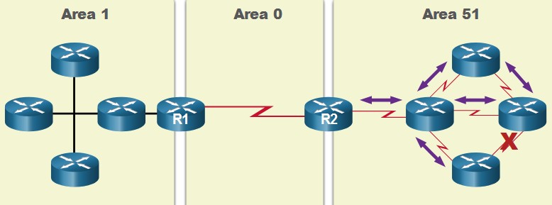
To make OSPF more efficient and scalable, OSPF supports hierarchical routing using areas. An OSPF area is a group of routers that share the same link-state information in their LSDBs. OSPF can be implemented in one of two ways, as follows:
- Single-Area OSPF – All routers are in one area. Best practice is to use area 0.
- Multiarea OSPF – OSPF is implemented using multiple areas, in a hierarchical fashion. All areas must connect to the backbone area (area 0). Routers interconnecting the areas are referred to as Area Border Routers (ABRs).
The focus of this module is on single-area OSPFv2. 
Multiarea OSPF
- The hierarchical-topology design options with multiarea OSPF can offer the following advantages.
- Smaller routing tables – Tables are smaller because there are fewer routing table entries. This is because network addresses can be summarized between areas. Route summarization is not enabled by default.
- Reduced link-state update overhead – Designing multiarea OSPF with smaller areas minimizes processing and memory requirements.
- Reduced frequency of SPF calculations -– Multiarea OSPF localize the impact of a topology change within an area. For instance, it minimizes routing update impact because LSA flooding stops at the area boundary.

OSPFv3
- OSPFv3 is the OSPFv2 equivalent for exchanging IPv6 prefixes. OSPFv3 exchanges routing information to populate the IPv6 routing table with remote prefixes.
- Note: With the OSPFv3 Address Families feature, OSPFv3 includes support for both IPv4 and IPv6. OSPF Address Families is beyond the scope of this curriculum.
- OSPFv3 has the same functionality as OSPFv2, but uses IPv6 as the network layer transport, communicating with OSPFv3 peers and advertising IPv6 routes. OSPFv3 also uses the SPF algorithm as the computation engine to determine the best paths throughout the routing domain.
- OSPFv3 has separate processes from its IPv4 counterpart. The processes and operations are basically the same as in the IPv4 routing protocol, but run independently.
OSPF Packets
Types of OSPF Packets
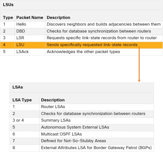
The table summarizes the five different types of Link State Packets (LSPs) used by OSPFv2. OSPFv3 has similar packet types.
| Type | Packet Name | Description |
| 1 | Hello | Discovers neighbors and builds adjacencies between them |
| 2 | Database Description (DBD) | Checks for database synchronization between routers |
| 3 | Link-State Request (LSR) | Requests specific link-state records from router to router |
| 4 | Link-State Update (LSU) | Sends specifically requested link-state records |
| 5 | Link-State Acknowledgment (LSAck) | Acknowledges the other packet types |
Link-State Updates

- LSUs are also used to forward OSPF routing updates. An LSU packet can contain 11 different types of OSPFv2 LSAs. OSPFv3 renamed several of these LSAs and also contains two additional LSAs.
- LSU and LSA are often used interchangeably, but the correct hierarchy is LSU packets contain LSA messages.
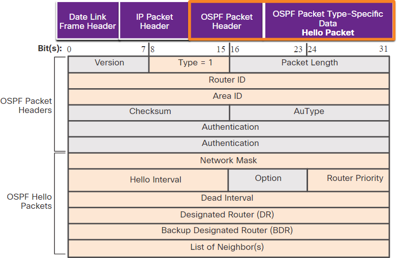
Hello Packet
 The OSPF Type 1 packet is the Hello packet. Hello packets are used to do the following:
- Discover OSPF neighbors and establish neighbor adjacencies.
- Advertise parameters on which two routers must agree to become neighbors.
- Elect the Designated Router (DR) and Backup Designated Router (BDR) on multiaccess networks like Ethernet. Point-to- point links do not require DR or BDR.
OSPF Operation
OSPF Operational States
| State | Description |
| Down State |
|
| Init State |
|
| Two-Way State |
|
| State | Description |
| ExStart State | On point-to-point networks, the two routers decide which router will initiate the DBD packet exchange and decide upon the initial DBD packet sequence number. |
| Exchange State |
|
| Loading State |
|
| Full State | The link-state database of the router is fully synchronized. |
Establish Neighbor Adjacencies
-
-
- To determine if there is an OSPF neighbor on the link, the router sends a Hello packet that contains its router ID out all OSPF-enabled interfaces. The Hello packet is sent to the reserved All OSPF Routers IPv4 multicast address 224.0.0.5. Only OSPFv2 routers will process these packets.
- The OSPF router ID is used by the OSPF process to uniquely identify each router in the OSPF area. A router ID is a 32-bit number formatted like an IPv4 address and assigned to uniquely identify a router among OSPF peers.
- When a neighboring OSPF-enabled router receives a Hello packet with a router ID that is not within its neighbor list, the receiving router attempts to establish an adjacency with the initiating router.
-
The process routers use to establish adjacency on a multiaccess network:
| 1 | Down to Init State | When OSPFv2 is enabled on the interface, R1 transitions from Down to Init and starts sending OSPFv2 Hellos out of the interface in an attempt to discover neighbors. |
| 2 | Init State | When a R2 receives a hello from the previously unknown router R1, it adds R1’s router ID to the neighbor list and responds with a Hello packet containing its own router ID. |
| 3 | Two-Way State | R1 receives R2’s hello and notices that the message contains the R1 router ID in the list of R2’s neighbors. R1 adds R2’s router ID to the neighbor list and transitions to the Two- Way State. If R1 and R2 are connected with a point-to-point link, they transition to ExStart If R1 and R2 are connected over a common Ethernet network, the DR/BDR election occurs. |
| 4 | Elect the DR & BDR | The DR and BDR election occurs, where the router with the highest router ID or highest priority is elected as the DR, and second highest is the BDR |
Synchronizing OSPF Databases
After the Two-Way state, routers transition to database synchronization states. This is a three step process, as follows:
-
-
-
- Decide first router: The router with the highest router ID sends its DBD first.
- Exchange DBDs: As many as needed to convey the database. The other router must acknowledge each DBD with an LSAck packet.
- Send an LSR: Each router compares the DBD information with the local LSDB. If the DBD has more current link information, the router transitions to the loading state.
-
-
After all LSRs have been exchanged and satisfied, the routers are considered synchronized and in a full state. Updates (LSUs) are sent:
-
-
-
- When a change is perceived (incremental updates)
- Every 30 minutes
-
-
The Need for a DR
 Multiaccess networks can create two challenges for OSPF regarding the flooding of LSAs, as follows:
-
-
- Creation of multiple adjacencies – Ethernet networks could potentially interconnect many OSPF routers over a common link. Creating adjacencies with every router would lead to an excessive number of LSAs exchanged between routers on the same network.
- Extensive flooding of LSAs – Link-state routers flood their LSAs any time OSPF is initialized, or when there is a change in the topology. This flooding can become excessive.
-
LSA Flooding with a DR
-
-
- An increase in the number of routers on a multiaccess network also increases the number of LSAs exchanged between the routers. This flooding of LSAs significantly impacts the operation of OSPF.
- If every router in a multiaccess network had to flood and acknowledge all received LSAs to all other routers on that same multiaccess network, the network traffic would become quite chaotic.
- On multiaccess networks, OSPF elects a DR to be the collection and distribution point for LSAs sent and received. A BDR is also elected in case the DR fails. All other routers become DROTHERs. A DROTHER is a router that is neither the DR nor the BDR.
- Note: The DR is only used for the dissemination of LSAs. The router will still use the best next- hop router indicated in the routing table for the forwarding of all other packets.
-