Basic Device Configuration
Module Objective: Configure devices using security best practices.
| Topic Title | Topic Objective |
|---|---|
| Configure a Switch with Initial Settings | Configure initial settings on a Cisco switch. |
| Configure Switch Ports | Configure switch ports to meet network requirements. |
| Secure Remote Access | Configure secure management access on a switch. |
| Basic Router Configuration | Configure basic settings on a router to route between two directly-connected networks, using CLI. |
| Verify Directly Connected Networks | Verify connectivity between two networks that are directly connected to a router. |
1.1 Configure a Switch with Initial Settings
Switch Boot Sequence
After a Cisco switch is powered on, it goes through the following five-step boot sequence:
- Step 1: First, the switch loads a power-on self-test (POST) program stored in ROM. POST checks the CPU subsystem. It tests the CPU, DRAM, and the portion of the flash device that makes up the flash file system.
- Step 2: Next, the switch loads the boot loader software. The boot loader is a small program stored in ROM that is run immediately after POST successfully completes.
- Step 3: The boot loader performs low-level CPU initialization. It initializes the CPU registers, which control where physical memory is mapped, the quantity of memory, and its speed.
- Step 4: The boot loader initializes the flash file system on the system board.
- Step 5: Finally, the boot loader locates and loads a default IOS operating system software image into memory and gives control of the switch over to the IOS.
The boot system Command
- The switch attempts to automatically boot by using information in the BOOT environment variable. If this variable is not set, the switch attempts to load and execute the first executable file it can find.
- The IOS operating system then initializes the interfaces using the Cisco IOS commands found in the startup-config file. The startup-config file is called config.text and is located in flash. In the example, the BOOT environment variable is set using the boot system global configuration mode command. Notice that the IOS is located in a distinct folder and the folder path is specified. Use the command show boot to see what the current IOS boot file is set to.

| Command | Definition |
|---|---|
| boot system | The main command |
| flash: | The storage device |
| c2960-lanbasek9-mz.150-2.SE/ | The path to the file system |
| c2960-lanbasek9-mz.150-2.SE.bin | The IOS file name |
Switch LED Indicators

- System LED (SYST): Shows whether the system is receiving power and functioning properly. Redundant Power Supply LED (RPS): Shows the RPS status.
- Port Status LED (STAT): When green, indicates port status mode is selected, which is the default. Port status can then be understood by the light associated with each port.
- Port Duplex LED (DUPLX): When green, indicates port duplex mode is selected. Port duplex can then be understood by the light associated with each port.
- Port Speed LED (SPEED): When green, indicates port speed mode is selected. Port speed can then be understood by the light associated with each port.
- Power over Ethernet LED (PoE): Present if the switch supports PoE. Indicates the PoE status of ports on the switch.
- The Mode button is used to move between the different modes – STAT, DUPLX, SPEED, and PoE

Recovering from a System Crash
The boot loader provides access into the switch if the operating system cannot be used because of missing or damaged system files. The boot loader has a command line that provides access to the files stored in flash memory. The boot loader can be accessed through a console connection following these steps:
- Step 1. Connect a PC by console cable to the switch console port. Configure terminal emulation software to connect to the switch.
- Step 2. Unplug the switch power cord.
- Step 3. Reconnect the power cord to the switch and, within 15 seconds, press and hold down the Mode button while the System LED is still flashing green.
- Step 4. Continue pressing the Mode button until the System LED turns briefly amber and then solid green; then release the Mode button.
- Step 5. The boot loader switch: prompt appears in the terminal emulation software on the PC. The boot loader command line supports commands to format the flash file system, reinstall the operating system software, and recover a lost or forgotten password. For example, the dir command can be used to view a list of files within a specified directory.
Switch Management Access
To prepare a switch for remote management access, the switch must be configured with an IP address and a subnet mask. To manage the switch from a remote network, the switch must be configured with a default gateway. This is very similar to configuring the IP address information on host devices. In the figure, the switch virtual interface (SVI) on S1 should be assigned an IP address. The SVI is a virtual interface, not a physical port on the switch. A console cable is used to connect to a PC so that the switch can be initially configured. 
Switch SVI Configuration Example
By default, the switch is configured to have its management controlled through VLAN 1. All ports are assigned to VLAN 1 by default. For security purposes, it is considered a best practice to use a VLAN other than VLAN 1 for the management VLAN, Step 1: Configure the Management Interface: From VLAN interface configuration mode, an IPv4 address and subnet mask is applied to the management SVI of the switch. Note: The SVI for VLAN 99 will not appear as “up/up” until VLAN 99 is created and there is a device connected to a switch port associated with VLAN 99. Note: The switch may need to be configured for IPv6. For example, before you can configure IPv6 addressing on a Cisco Catalyst 2960 running IOS version 15.0, you will need to enter the global configuration command sdm prefer dual-ipv4-and-ipv6 default and then reload the switch.
| Task | Command |
|---|---|
| Enter global configuration mode. | S1# configure terminal |
| Enter interface configuration mode for the SVI. | S1(config)# interface vlan 99 |
| Configure the management interface IPv4 address. | S1(config-if)# ip address 172.17.99.11 255.255.255.0 |
| Configure the management interface IPv6 address. | S1(config-if)# ipv6 address 2001:db8:acad:99::1/64 |
| Enable the management interface. | S1(config-if)# no shutdown |
| Return to the privileged EXEC mode. | S1(config-if)# end |
| Save the running config to the startup config. | S1# copy running-config startup-config |
Step 2: Configure the Default Gateway The switch should be configured with a default gateway if it will be managed remotely from networks that are not directly connected. Note: Because, it will receive its default gateway information from a router advertisement (RA) message, the switch does not require an IPv6 default gateway.
| Task | Command |
|---|---|
| Enter global configuration mode. | S1# configure terminal |
| Configure the default gateway for the switch. | S1(config)# ip default-gateway 172.17.99.1 |
| Return to the privileged EXEC mode. | S1(config-if)# end |
| Save the running config to the startup config. | S1# copy running-config startup-config |
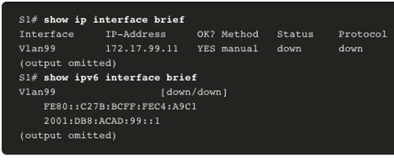
Step 3: Verify Configuration The show ip interface brief and show ipv6 interface brief commands are useful for determining the status of both physical and virtual interfaces. The output shown confirms that interface VLAN 99 has been configured with an IPv4 and IPv6 address. Note: An IP address applied to the SVI is only for remote management access to the switch; this does not allow the switch to route Layer 3 packets.