
Data Access
|
Addresses
- Both the data link and network layers use addressing to deliver data from source to destination.
- Network layer source and destination addresses – Responsible for delivering the IP packet from original source to the final destination.
- Data link layer source and destination addresses – Responsible for delivering the data link frame from one network interface card (NIC) to another NIC on the same network.

Layer 3 Logical Address
The IP packet contains two IP addresses:
- Source IP address – The IP address of the sending device, original source of the packet.
- Destination IP address – The IP address of the receiving device, final destination of the packet.
 These addresses may be on the same link or remote. An IP address contains two parts: Network portion (IPv4) or Prefix (IPv6)
- The left-most part of the address indicates the network group which the IP address is a member.
- Each LAN or WAN will have the same network portion.
Host portion (IPv4) or Interface ID (IPv6)
- The remaining part of the address identifies a specific device within the group.
- This portion is unique for each device on the network.
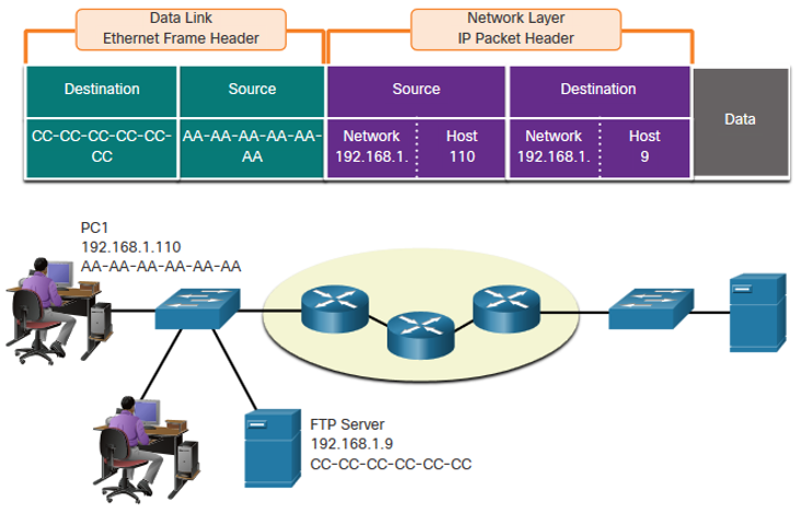
Devices on the Same Network
When devices are on the same network the source and destination will have the same number in network portion of the address.
- PC1 – 192.168.1.110
- FTP Server – 192.168.1.9
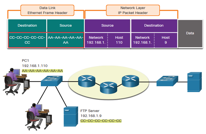
Role of the Data Link Layer Addresses: Same IP Network
When devices are on the same Ethernet network the data link frame will use the actual MAC address of the destination NIC. MAC addresses are physically embedded into the Ethernet NIC and are local addressing.
- The Source MAC address will be that of the originator on the link.
- The Destination MAC address will always be on the same link as the source, even if the ultimate destination is remote.
Devices on a Remote Network
- What happens when the actual (ultimate) destination is not on the same LAN and is remote?
- What happens when PC1 tries to reach the Web Server?
- Does this impact the network and data link layers?

Role of the Network Layer Addresses
When the source and destination have a different network portion, this means they are on different networks.
- PC1 – 192.168.1
- Web Server – 172.16.1
 When the final destination is remote, Layer 3 will provide Layer 2 with the local default gateway IP address, also known as the router address.
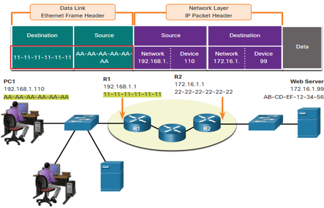
- The default gateway (DGW) is the router interface IP address that is part of this LAN and will be the “door” or “gateway” to all other remote locations.
- All devices on the LAN must be told about this address or their traffic will be confined to the LAN only.
- Once Layer 2 on PC1 forwards to the default gateway (Router), the router then can start the routing process of getting the information to actual destination.
- The data link addressing is local addressing so it will have a source and destination for each link.
- The MAC addressing for the first segment is : Source – AA-AA-AA-AA-AA-AA (PC1) Sends the frame. Destination – 11-11-11-11-11-11 (R1- Default Gateway MAC) Receives the frame.
Note: While the L2 local addressing will change from link to link or hop to hop, the L3 addressing remains the same.
Data Link Addresses
Since data link addressing is local addressing, it will have a source and destination for each segment or hop of the journey to the destination. The MAC addressing for the first segment is:
- Source – (PC1 NIC) sends frame
- Destination – (First Router- DGW interface) receives frame
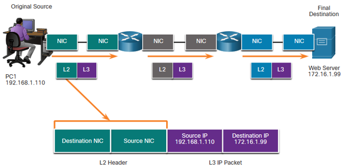 The MAC addressing for the second hop is:
- Source – (First Router- exit interface) sends frame
- Destination – (Second Router) receives frame
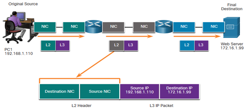 The MAC addressing for the last segment is:
- Source – (Second Router- exit interface) sends frame
- Destination – (Web Server NIC) receives frame
 Notice that the packet is not modified, but the frame is changed, therefore the L3 IP addressing does not change from segment to segment like the L2 MAC addressing. The L3 addressing remains the same since it is global and the ultimate destination is still the Web Server.
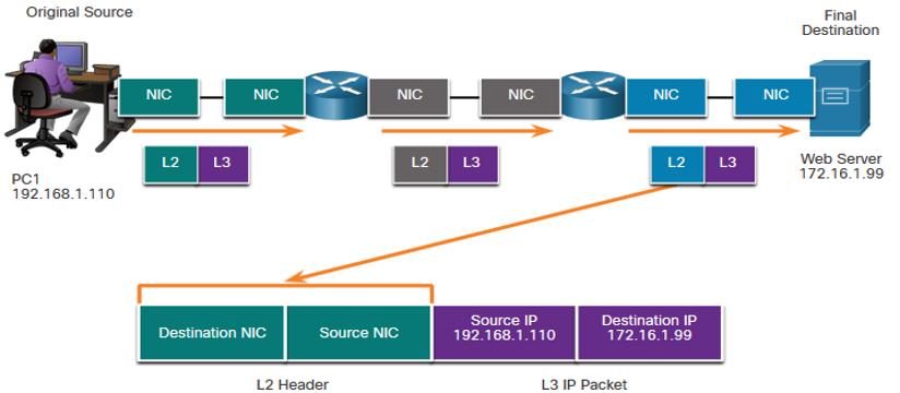
Other related topics
| Topic Title | Topic Objective |
|---|---|
| The Rules in Network Communications | Describe the types of rules that are necessary to successfully communicate. |
| Protocols | Explain why protocols are necessary in network communication. |
| Protocol Suites | Explain the purpose of adhering to a protocol suite. |
| Standards Organizations | Explain the role of standards organizations in establishing protocols for network interoperability. |
| Reference Models | Explain how the TCP/IP model and the OSI model are used to facilitate standardization in the communication process. |
| Data Encapsulation | Explain how data encapsulation allows data to be transported across the network. |
| Data Access | Explain how local hosts access local resources on a network. |
Other useful information
- Full CCNA Course
- CCNA Certificate Information
- 200-301 CCNA Exam Questions and Solutions
- 200-301 CCNA Exam Topics