
Module Title: Network Management Module Objective: Implement protocols to manage the network.
| Topic Title | Topic Objective |
| Device Discovery with CDP | Use CDP to map a network topology. |
| Device Discovery with LLDP | Use LLDP to map a network topology. |
| NTP | Implement NTP between an NTP client and NTP server. |
| SNMP | Explain how SNMP operates. |
| Syslog | Explain syslog operation. |
| Router and Switch File Maintenance | Use commands to back up and restore an IOS configuration file. |
| IOS Image Management | Implement protocols to manage the network. |
Device Discovery with CDP
CDP Overview
CDP is a Cisco proprietary Layer 2 protocol that is used to gather information about Cisco devices which share the same data link. CDP is media and protocol independent and runs on all Cisco devices, such as routers, switches, and access servers. The device sends periodic CDP advertisements to connected devices. These advertisements share information about the type of device that is discovered, the name of the devices, and the number and type of the interfaces. 
Configure and Verify CDP
- For Cisco devices, CDP is enabled by default. To verify the status of CDP and display information about CDP, enter the show cdp command.
- To disable CDP on a specific interface, enter no cdp enable in the interface configuration mode. CDP is still enabled on the device; however, no more CDP advertisements will be sent out that interface. To enable CDP on the specific interface again, enter cdp enable.
- To enable CDP globally for all the supported interfaces on the device, enter cdp run in the global configuration mode. CDP can be disabled for all the interfaces on the device with the no cdp run command in the global configuration mode.
- Use the show cdp interface command to display the interfaces that are CDP- enabled on a device. The status of each interface is also displayed.
Discover Devices by Using CDP
- With CDP enabled on the network, the show cdp neighbors command can be used to determine the network layout, as shown in the output.
- The output shows that there is another Cisco device, S1, connected to the G0/0/1 interface on R1. Furthermore, S1 is connected through its F0/5
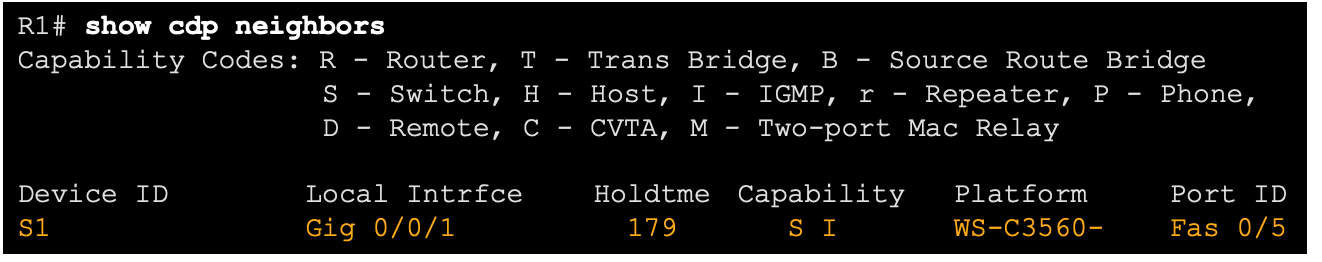
The network administrator uses show cdp neighbors detail to discover the IP address for S1. As displayed in the output, the address for S1 is 192.168.1.2. 
Device Discovery with LLDP
LLDP Overview
Link Layer Discovery Protocol (LLDP) is a vendor-neutral neighbor discovery protocol similar to CDP. LLDP works with network devices, such as routers, switches, and wireless LAN access points. This protocol advertises its identity and capabilities to other devices and receives the information from a physically-connected Layer 2 device. 
Configure and Verify LLDP
- LLDP may be enabled by default. To enable LLDP globally on a Cisco network device, enter the lldp run command in the global config mode. To disable LLDP, enter the no lldp run command in the global config mode.
- LLDP can be configured on specific interfaces. However, LLDP must be configured separately to transmit and receive LLDP packets.
- To verify LLDP is enabled, enter the show lldp command in privileged EXEC mode.

Discover Devices by Using LLDP
With LLDP enabled, device neighbors can be discovered by using the show lldp neighbors command. 
Discover Devices by Using LLDP (Cont.)
When more details about the neighbors are needed, the show lldp neighbors detail command can provide information, such as the neighbor IOS version, IP address, and device capability. 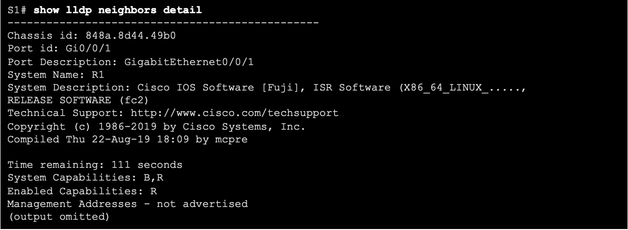
NTP
Time and Calendar Services
- The software clock on a router or switch starts when the system boots. It is the primary source of time for the system. It is important to synchronize the time across all devices on the network. When the time is not synchronized between devices, it will be impossible to determine the order of the events and the cause of an event.
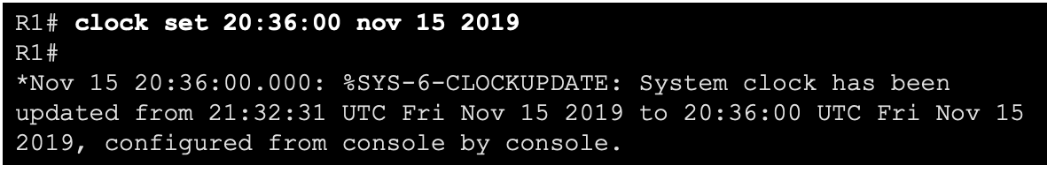
- Typically, the date and time settings on a router or switch can be set by using one of two methods You can manually configure the date and time, as shown in the example, or configure the Network Time Protocol (NTP).
As a network grows, it becomes difficult to ensure that all infrastructure devices are operating with synchronized time using the manual method. A better solution is to configure the NTP on the network. This protocol allows routers on the network to synchronize their time settings with an NTP server, which provides more consistent time settings. NTP can be set up to synchronize to a private master clock, or it can synchronize to a publicly available NTP server on the internet. NTP uses UDP port 123 and is documented in RFC 1305.
NTP Operation
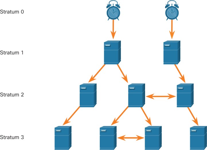 NTP networks use a hierarchical system of time sources. Each level in this hierarchical system is called a stratum. The stratum level is defined as the number of hop counts from the authoritative source. The synchronized time is distributed across the network by using NTP. The max hop count is 15. Stratum 16, the lowest stratum level, indicates that a device is unsynchronized.
NTP Operation (Cont.)
- Stratum 0: These authoritative time sources are high-precision timekeeping devices assumed to be accurate and with little or no delay associated with them.
- Stratum 1: Devices that are directly connected to the authoritative time sources. They act as the primary network time standard.
- Stratum 2 and Lower: Stratum 2 servers are connected to stratum 1 devices through network connections. Stratum 2 devices, such as NTP clients, synchronize their time by using the NTP packets from stratum 1 servers. They could also act as servers for stratum 3 devices.
Time servers on the same stratum level can be configured to act as a peer with other time servers on the same stratum level for backup or verification of time.
Configure and Verify NTP
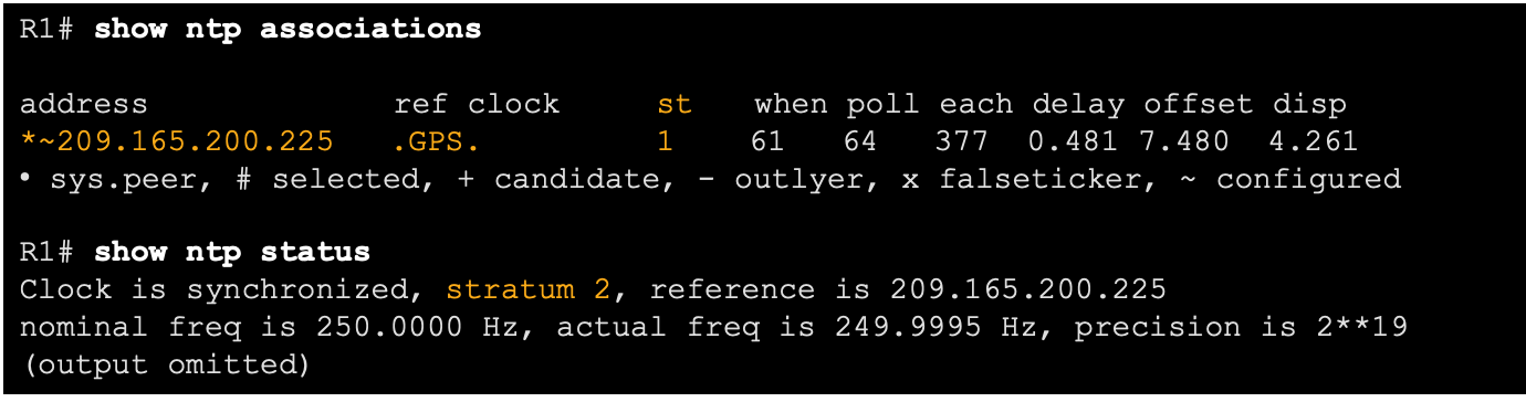
- Before NTP is configured on the network, the show clock command displays the current time on the software clock. With the detail option, notice that the time source is user configuration. That means the time was manually configured with the clock command.
- The ntp server ip-address command is issued in global configuration mode to configure 209.165.200.225 as the NTP server for R1. To verify the time source is set to NTP, use the show clock detail command. Notice that now the time source is NTP.

- The show ntp associations and show ntp status commands are used to verify that R1 is synchronized with the NTP server at 209.165.200.225. Notice that R1 is synchronized with a stratum 1 NTP server at 209.165.200.225, which is synchronized with a GPS clock. The show ntp status command displays that R1 is now a stratum 2 device that is synchronized with the NTP server at 209.165.220.225.
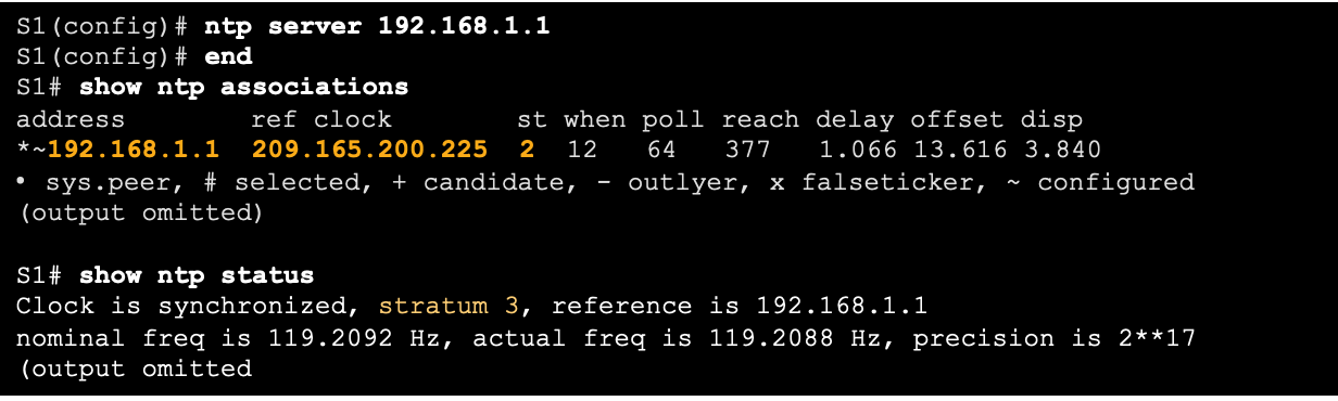
- The clock on S1 is configured to synchronize to R1 with the ntp server command and the configuration is verified with the show ntp associations command.
- Output from the show ntp associations command verifies that the clock on S1 is now synchronized with R1 at 192.168.1.1 via NTP. R1 is a stratum 2 device, making S1 is a stratum 3 device that can provide NTP service to other devices in the network.
SNMP
Introduction to SNMP
SNMP was developed to allow administrators to manage nodes on an IP network. It enables network administrators to monitor and manage network performance, find and solve network problems, and plan for network growth. SNMP is an application layer protocol that provides a message format for communication between managers and agents. The SNMP system consists of three elements:
-
-
- SNMP manager
- SNMP agents (managed node)
- Management Information Base (MIB)
-
SNMP defines how management information is exchanged between network management applications and management agents. The SNMP manager polls the agents and queries the MIB for SNMP agents on UDP port 161. SNMP agents send any SNMP traps to the SNMP manager on UDP port 162. 
- The SNMP manager is part of a network management system (NMS). The SNMP manager can collect information from an SNMP agent by using the “get” action and can change configurations on an agent by using the “set” action. SNMP agents can forward information directly to a network manager by using “traps”.
- The SNMP agent and MIB reside on SNMP client devices. MIBs store data about the device and operational statistics and are meant to be available to authenticated remote users. The SNMP agent is responsible for providing access to the local MIB.
SNMP Operation
- SNMP agents that reside on managed devices collect and store information about the device and its operation locally in the MIB. The SNMP manager then uses the SNMP agent to access information within the MIB.
- There are two primary SNMP manager requests, get and set. In addition to configuration, a set can cause an action to occur, like restarting a router.
| Operation | Description |
| get-request | Retrieves a value from a specific variable. |
| get-next-request | Retrieves a value from a variable within a table; the SNMP manager does not need to know the exact variable name. A sequential search is performed to find the needed variable from within a table. |
| get-bulk-request | Retrieves large blocks of data, such as multiple rows in a table, that would otherwise require the transmission of many small blocks of data. (Only works with SNMPv2 or later.) |
| get-response | Replies to a get-request, get-next-request, and set-request sent by an NMS. |
| set-request | Stores a value in a specific variable. |
The SNMP agent responds to SNMP manager requests as follows:
-
- Get an MIB variable – The SNMP agent performs this function in response to a GetRequest-PDU from the network manager. The agent retrieves the value of the requested MIB variable and responds to the network manager with that value.
- Set an MIB variable – The SNMP agent performs this function in response to a SetRequest-PDU from the network manager. The SNMP agent changes the value of the MIB variable to the value specified by the network manager. An SNMP agent reply to a set request includes the new settings in the device.

SNMP Agent Traps
-
- Traps are unsolicited messages alerting the SNMP manager to a condition or event on the network. Trap-directed notifications reduce network and agent resources by eliminating the need for some of SNMP polling requests.
- The figure illustrates the use of an SNMP trap to alert the network administrator that interface G0/0/0 has failed. The NMS software can send the network administrator a text message, pop up a window on the NMS software, or turn the router icon red in the NMS GUI.

SNMP Versions
-
- SNMPv1 – Legacy standard defined in RFC 1157. Uses a simple community-string based authentication method. Should not be used due to security risks.
- SNMPv2c – Defined in RFCs 1901-1908. Uses a simple community-string based authentication method. Provides for bulk retrieval options, as well as more detailed error messages.
- SNMPv3 – Defined in RFCs 3410-3415. Uses username authentication, provides data protection using HMAC-MD5 or HMAC-SHA and encryption using DES, 3DES, or AES encryption.
Community Strings
SNMPv1 and SNMPv2c use community strings that control access to the MIB. Community strings are plaintext passwords. SNMP community strings authenticate access to MIB objects. There are two types of community strings:
-
-
- Read-only (ro) – This type provides access to the MIB variables, but does not allow these variables to be changed, only read. Because security is minimal in version 2c, many organizations use SNMPv2c in read-only mode.
- Read-write (rw) – This type provides read and write access to all objects in the MIB.
-
To view or set MIB variables, the user must specify the appropriate community string for read or write access.
MIB Object ID
The MIB organizes variables hierarchically. Formally, the MIB defines each variable as an object ID (OID). OIDs uniquely identify managed objects. The MIB organizes the OIDs based on RFC standards into a hierarchy of OIDs, usually shown as a tree.
-
- The MIB tree for any given device includes some branches with variables common to many networking devices and some branches with variables specific to that device or vendor.
- RFCs define some common public variables. Most devices implement these MIB variables. In addition, networking equipment vendors, like Cisco, can define their own private branches of the tree to accommodate new variables specific to their devices.

The figure shows portions of the MIB structure defined by Cisco. Note how the OID can be described in words or numbers to help locate a particular variable in the tree. OIDs belonging to Cisco, are numbered as follows: .iso (1).org (3).dod (6).internet (1).private (4).enterprises (1).cisco (9). Therefore, the OID is 1.3.6.1.4.1.9.
SNMP Polling Scenario
-
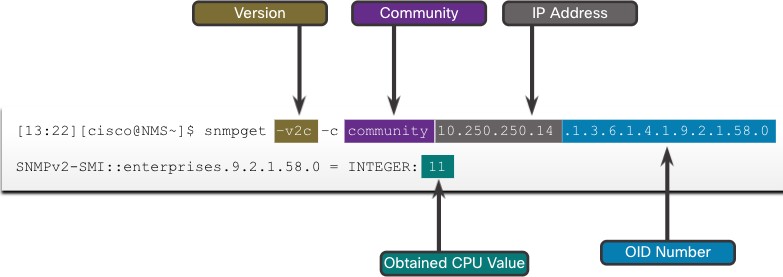
- SNMP can be used is to observe CPU utilization over a period of time by polling devices. CPU statistics can then be compiled on the NMS and graphed. This creates a baseline for the network administrator.
- The data is retrieved via the snmpget utility, issued on the NMS. Using the snmpget utility, you can manually retrieve real-time data, or have the NMS run a report. This report would give you a period of time that you could use the data to get the average.
SNMP Object Navigator
The snmpget utility gives some insight into the basic mechanics of how SNMP works. However, working with long MIB variable names like 1.3.6.1.4.1.9.2.1.58.0 can be problematic for the average user. More commonly, the network operations staff uses a network management product with an easy-to-use GUI, which makes the entire MIB data variable naming transparent to the user. 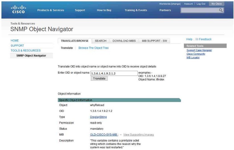 The Cisco SNMP Navigator on the http://www.cisco.com website allows a network administrator to research details about a particular OID.
Syslog
Introduction to Syslog
Syslog uses UDP port 514 to send event notification messages across IP networks to event message collectors, as shown in the figure. The syslog logging service provides three primary functions, as follows:
-
-
- The ability to gather logging information for monitoring and troubleshooting
- The ability to select the type of logging information that is captured
- The ability to specify the destinations of captured syslog messages
-

Syslog Operation
The syslog protocol starts by sending system messages and debug output to a local logging process. Syslog configuration may send these messages across the network to an external syslog server, where they can be retrieved without needing to access the actual device. Alternatively, syslog messages may be sent to an internal buffer. Messages sent to the internal buffer are only viewable through the CLI of the device. The network administrator may specify that only certain types of system messages be sent to various destinations. Popular destinations for syslog messages include the following:
- Logging buffer (RAM inside a router or switch)
- Console line
- Terminal line
- Syslog server
Syslog Message Format
Cisco devices produce syslog messages as a result of network events. Every syslog message contains a severity level and a facility.
| Severity Name | Severity Level | Explanation |
| Emergency | Level 0 | System Unusable |
| Alert | Level 1 | Immediate Action Needed |
| Critical | Level 2 | Critical Condition |
| Error | Level 3 | Error Condition |
| Warning | Level 4 | Warning Condition |
| Notification | Level 5 | Normal, but Significant Condition |
| Informational | Level 6 | Informational Message |
| Debugging | Level 7 | Debugging Message |
The smaller numerical levels are the more critical syslog alarms. The severity level of the messages can be set to control where each type of message is displayed (i.e. on the console or the other destinations). The complete list of syslog levels is shown in the table.
Syslog Facilities
In addition to specifying the severity, syslog messages also contain information on the facility. Syslog facilities are service identifiers that identify and categorize system state data for error and event message reporting. The logging facility options that are available are specific to the networking device. Some common syslog message facilities reported on Cisco IOS routers include:
-
- IP
- OSPF protocol
- SYS operating system
- IP security (IPsec)
- Interface IP (IF)
By default, the format of syslog messages on the Cisco IOS Software is as follows: %facility-severity-MNEMONIC: description For example, sample output on a Cisco switch for an EtherChannel link changing state to up is: %LINK-3-UPDOWN: Interface Port-channel1, changed state to up Here the facility is LINK and the severity level is 3, with a MNEMONIC of UPDOWN.
Configure Syslog Timestamp
By default, log messages are not timestamped. Log messages should be timestamped so that when they are sent to another destination, such as a Syslog server, there is record of when the message was generated. Use the command service timestamps log datetime to force logged events to display the date and time. 
Router and Switch File Maintenance
Router File Systems
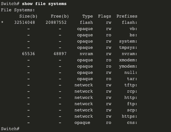
The Cisco IOS File System (IFS) allows the administrator to navigate to different directories and list the files in a directory. The administrator can also create subdirectories in flash memory or on a disk. The directories available depend on the device. The example displays the output of the show file systems command, which lists all of the available file systems on a Cisco 4221 router.  The asterisk indicates the current default file system. The pound sign (#) indicates a bootable disk. Both of these are assigned to the flash file system by default

Because flash is the default file system, the dir command lists the contents of flash. Of specific interest is the last listing. This is the name of the current Cisco IOS file image that is running in RAM. 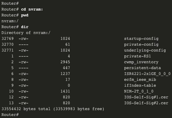 To view the contents of NVRAM, you must change the current default file system by using the cd (change directory) command, as shown in the example. The present working directory command is pwd. This command verifies that we are viewing the NVRAM directory. Finally, the dir command lists the contents of NVRAM. Although there are several configuration files listed, of specific interest is the startup- configuration file.
Switch File Systems
 With the Cisco 2960 switch flash file system, you can copy configuration files, and archive (upload and download) software images. The command to view the file systems on a Catalyst switch is the same as on a Cisco router: show file systems.
Use a Text File to Back Up a Configuration
 Configuration files can be saved to a text file by using Tera Term: Step 1. On the File menu, click Log. Step 2. Choose the location to save the file. Tera Term will begin capturing text. Step 3. After capture has been started, execute the show running-config or show startup- config command at the privileged EXEC prompt. Text displayed in the terminal window will be directed to the chosen file. Step 4. When the capture is complete, select Close in the Tera Term: Log window. Step 5. View the file to verify that it was not corrupted.
Use a Text File to Restore a Configuration
A configuration can be copied from a file and then directly pasted to a device. The file will require editing to ensure that encrypted passwords are in plaintext, and that non-command text such as –More– and IOS messages are removed. In addition, you may want to add enable and configure terminal to the beginning of the file or enter global configuration mode before pasting the configuration. Instead of copying and pasting, a configuration can be restored from a text file by using Tera Term. When using Tera Term, the steps are as follows: Step 1. On the File menu, click Send file. Step 2. Locate the file to be copied into the device and click Open. Step 3. Tera Term will paste the file into the device. The text in the file will be applied as commands in the CLI and become the running configuration on the device.
Using TFTP to Back Up and Restore a Configuration
Follow these steps to back up the running configuration to a TFTP server: Step 1. Enter the copy running-config tftp command. Step 2. Enter the IP address of the host where the configuration file will be stored. Step 3. Enter the name to assign to the configuration file. Step 4. Press Enter to confirm each choice. Use the following steps to restore the running configuration from a TFTP server: Step 1. Enter the copy tftp running-config command. Step 2. Enter the IP address of the host where the configuration file is stored. Step 3. Enter the name to assign to the configuration file. Step 4. Press Enter to confirm each choice. R1# copy running-config tftp Remote host []?192.168.10.254 Name of the configuration file to write[R1-config]? R1-Jan-2019 Write file R1-Jan-2019 to 192.168.10.254? [confirm] Writing R1-Jan-2019 !!!!!! [OK]
USB Ports on a Cisco Router
The Universal Serial Bus (USB) storage feature enables certain models of Cisco routers to support USB flash drives. The USB flash feature provides an optional secondary storage capability and an additional boot device. The USB ports of a Cisco 4321 Router are shown in the figure. Use the dir command to view the contents of the USB flash drive. 
Using USB to Back Up and Restore a Configuration
- Issue the show file systems command to verify that the USB drive is there and confirm its name. For this example, the USB file system is named usbflash0:.
- Use the copy run usbflash0:/ command to copy the configuration file to the USB flash drive. Be sure to use the name of the flash drive, as indicated in the file system. The slash is optional but indicates the root directory of the USB flash drive.
- The IOS will prompt for the filename. If the file already exists on the USB flash drive, the router will prompt to overwrite.
 Use the dir command to see the file on the USB drive and use the more command to see the contents. To Restore Configurations with a USB Flash Drive, it will be necessary to edit the USB R1-Config file with a text editor. Assuming the file name is R1-Config, use the command copy usbflash0:/R1- Config running-config to restore a running configuration.
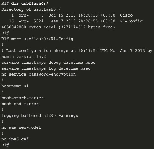
Password Recovery Procedures
Passwords on devices are used to prevent unauthorized access. For encrypted passwords, such as the enable secret passwords, the passwords must be replaced after recovery. Depending on the device, the detailed procedure for password recovery varies. However, all the password recovery procedures follow the same principle: Step 1. Enter the ROMMON mode. Step 2. Change the configuration register. Step 3. Copy the startup-config to the running-config. Step 4. Change the password. Step 5. Save the running-config as the new startup-config. Step 6. Reload the device.
Password Recovery Example
Step 1. Enter the ROMMON mode. With console access, a user can access the ROMMON mode by using a break sequence during the boot up process or removing the external flash memory when the device is powered off. When successful, the rommon 1 > prompt displays, as shown in the example. 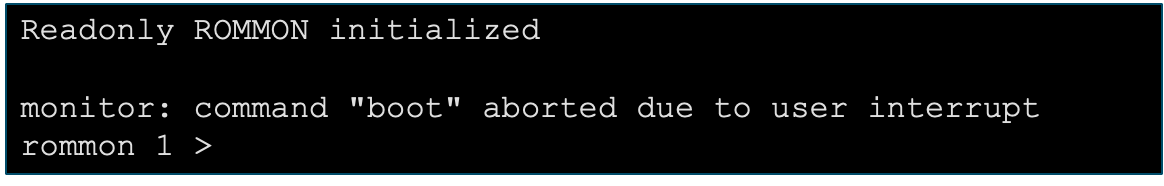 Step 2. Change the configuration register. The confreg 0x2142 command allows the user to set the configuration register to 0x2142, which causes the device to ignore the startup config file during startup. After setting the configuration register to 0x2142, type reset at the prompt to restart the device. Enter the break sequence while the device is rebooting and decompressing the IOS. The example displays the terminal output of a 1941 router in the ROMMON mode after using a break sequence during the boot up process.
  Step 3. Copy the startup-config to the running-config. After the device has finished reloading, issue the copy startup-config running-config command. CAUTION: Do not enter copy running-config startup-config. This command erases your original startup configuration.
  Step 4. Change the password. Because you are in privileged EXEC mode, you can now configure all the necessary passwords. Note: The password cisco is not a strong password and is used here only as an example
  Step 5. Save the running-config as the new startup-config. After the new passwords are configured, change the configuration register back to 0x2102 by using the config- register 0x2102 command in the global configuration mode. Save the running-config to startup-config.
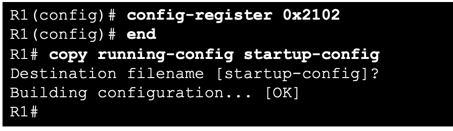
IOS Image Management
TFTP Servers as a Backup Location
As a network grows, Cisco IOS Software images and configuration files can be stored on a central TFTP server. This helps to control the number of IOS images and the revisions to those IOS images, as well as the configuration files that must be maintained. Production internetworks usually span wide areas and contain multiple routers. For any network, it is good practice to keep a backup copy of the Cisco IOS Software image in case the system image on the router becomes corrupted or accidentally erased. Widely distributed routers need a source or backup location for Cisco IOS Software images. Using a network TFTP server allows image and configuration uploads and downloads over the network. The network TFTP server can be another router, a workstation, or a host system.
Backup IOS Image to TFTP Server Example
To maintain network operations with minimum down time, it is necessary to have procedures in place for backing up Cisco IOS images. This allows the network administrator to quickly copy an image back to a router in case of a corrupted or erased image. Use the following steps: Step 1. Ping the TFTP server. Ping the TFTP server to test connectivity. Step 2. Verify image size in flash. Verify that the TFTP server has sufficient disk space to accommodate the Cisco IOS Software image. Use the show flash0: command on the router to determine the size of the Cisco IOS image file. Step 3. Copy the image to the TFTP server. Copy the image to the TFTP server by using the copy source-url destination-url command. After issuing the command by using the specified source and destination URLs, the user is prompted for the source file name, IP address of the remote host, and destination file name. The transfer will then begin.
Copy an IOS Image to a Device Example
Step 1. Ping the TFTP server. Ping the TFTP server to test connectivity. Step 2. Verify the amount of free flash. Ensure that there is sufficient flash space on the device being upgraded by using the show flash: command. Compare the free flash space with the new image file size. Step 3. Copy the IOS image file from the TFTP server to the router by using the copy tftp: flash: command. After issuing this command, the user will be prompted for the IP address of the remote host, source file name, and destination file name. 
The boot system Command
During startup, the bootstrap code parses the startup configuration file in NVRAM for the boot system commands that specify the name and location of the Cisco IOS Software image to load. Several boot system commands can be entered in sequence to provide a fault-tolerant boot plan. If there are no boot system commands in the configuration, the router defaults to loading the first valid Cisco IOS image in flash memory and runs it. To upgrade to the copied IOS image after that image is saved on the flash memory of the router, configure the router to load the new image by using the boot system command. Save the configuration. Reload the router to boot the router with new image. 