
Module Title: Network Troubleshooting Module Objective: Troubleshoot enterprise networks.
| Topic Title | Topic Objective |
| Network Documentation | Explain how network documentation is developed and used to troubleshoot network issues. |
| Troubleshooting Process | Compare troubleshooting methods that use a systematic, layered approach. |
| Troubleshooting Tools | Describe different networking troubleshooting tools. |
| Symptoms and Causes of Network Problems | Determine the symptoms and causes of network problems using a layered model. |
| Troubleshooting IP Connectivity | Troubleshoot a network using the layered model. |
Network Documentation
Documentation Overview
Accurate and complete network documentation is required to effectively monitor and troubleshoot networks. Common network documentation includes the following:
- Physical and logical network topology diagrams
- Network device documentation that records all pertinent device information
- Network performance baseline documentation
All network documentation should be kept in a single location and backup documentation should be maintained and kept in a separate location.
Network Topology Diagrams
There are two types of network topology diagrams: physical and logical.  Physical Topology
  Logical Topology
Network Device Documentation
Router Device Network device documentation should contain accurate, up-to- date records of the network hardware and software. Router Device Documentation  Switch Device Documentation
 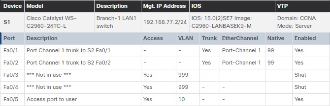 End-System Documentation
  Documentation should include all pertinent information about the network devices.
Establish a Network Baseline
A network baseline is used to establish normal network performance to determine the “personality” of a network under normal conditions. Establishing a network performance baseline requires collecting performance data from the ports and devices that are essential to network operation. The baseline data is as follows:
- Provides insight into whether the current network design can meet business requirements.
- Can reveal areas of congestion or areas in the network that are underutilized.
Step 1 – Determine What Types of Data to Collect
When conducting the initial baseline, start by selecting a few variables that represent the defined policies. If too many data points are selected, the amount of data can be overwhelming, making analysis of the collected data difficult. Start out simply and fine-tune along the way. Some good starting variables are interface utilization and CPU utilization.
Step 2 – Identify Devices and Ports of Interest
 A logical network topology can be useful in identifying key devices and ports to monitor. As shown in the sample topology, the devices and ports of interest include:
- PC1 (the Admin terminal)
- Two servers (i.e., Srv1 and Svr2)
- Router interfaces
- Key ports on switches
Step 3 – Determine the Baseline Duration
When capturing data for analysis, the period specified should be:
- At a minimum, seven days long.
- Last no more than six weeks, unless specific long-term trends need to be measured.
- Generally, a two-to-four-week baseline is adequate.
Conduct an annual analysis of the entire network, or baseline different sections of the network on a rotating basis. Analysis must be conducted regularly to understand how the network is affected by growth and other changes.
Data Measurement
The table lists some of the most common Cisco IOS commands used for data collection.
| Command | Description |
| show version |
|
| show ip interface [brief] show ipv6 interface [brief] |
|
| show interfaces |
|
| show ip route [static | eigrp | ospf | bgp] show ipv6 route [static | eigrp | ospf | bgp] |
|
| show cdp neighbors detail |
|
| show arp show ipv6 neighbors |
|
| show running-config |
|
| show vlan |
|
| show port |
|
| show tech-support |
|
Troubleshooting Process
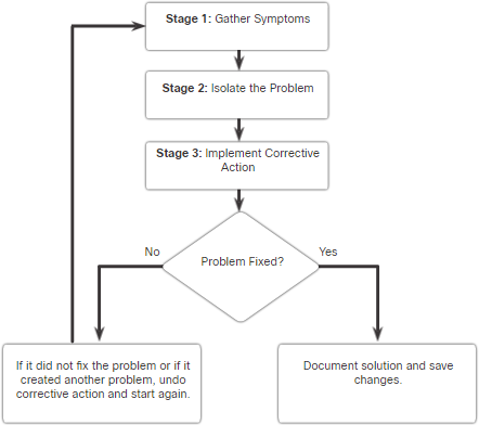
General Troubleshooting Procedures
Troubleshooting can be time consuming because networks differ, problems differ, and troubleshooting experience varies.
- Using a structured troubleshooting method will shorten overall troubleshooting time.
- There are several troubleshooting processes that can be used to solve a problem.
- The figure displays the logic flowchart of a simplified three-stage troubleshooting process.

Seven-Step Troubleshooting Process
The figure displays a more detailed seven- step troubleshooting process.
| Steps | Description |
| Define the Problem |
|
| Gather Information |
|
| Analyze Information |
|
| Eliminate Possible Causes |
|
| Propose Hypothesis |
|
| Test Hypothesis |
|
| Solve the Problem |
|
Question End Users
The table provides questioning guidelines and sample open ended end-user questions.
| Guidelines | Example Open Ended End-User Questions |
| Ask pertinent questions. |
|
| Determine the scope of the problem. |
|
| Determine when the problem occurred / occurs. |
|
| Determine if the problem is constant or intermittent. |
|
| Determine if anything has changed. |
|
| Use questions to eliminate or discover possible problems. |
|
Gather Information
Common Cisco IOS commands used to gather network problem symptoms.
| Command | Description |
| ping {host |ip-address} |
|
| traceroute destination |
|
| telnet {host | ip-address} |
|
| ssh -l user-id ip-address |
|
| show ip interface brief show ipv6 interface brief |
|
| show ip route show ipv6 route |
|
| show protocols |
|
| debug |
|
Troubleshooting with Layered Models
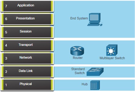 The OSI and TCP/IP models can be applied to isolate network problems when troubleshooting. The figure shows some common devices and the OSI layers that must be examined during the troubleshooting process for that device.
Structured Troubleshooting Methods
Different troubleshooting approaches that can be used include the following.
| Troubleshooting Approach | Description |
| Bottom-Up |
|
| Top-Down |
|
| Divide-and-Conquer |
|
| Follow-the-Path |
|
| Substitution |
|
| Comparison |
|
| Educated guess |
|
Guidelines for Selecting a Troubleshooting Method
 To quickly resolve network problems, take the time to select the most effective network troubleshooting method.
- The figure illustrates which method could be used when a certain type of problem is discovered.
- Troubleshooting is a skill that is developed by doing it.
- Every network problem you identify and solve gets added to your skill set.
Troubleshooting Process
Software Troubleshooting Tools
Common software troubleshooting tools include the following:
| Software Tool | Description |
| Network Management System Tools |
|
| Knowledge Bases |
|
| Baselining Tools |
|
Protocol Analyzers
 A protocol analyzer can capture and display the physical layer to the application layer information contained in a packet. Protocol analyzers, such as Wireshark, can help troubleshoot network performance problems.
Hardware Troubleshooting Tools
There are multiple types of hardware troubleshooting tools.
| Hardware Tools | Description |
| Digital Multimeters | Devices measure electrical values of voltage, current, and resistance. |
| Cable Testers | Handheld devices are designed for testing the various types of data communication cabling. |
| Cable Analyzers | Multifunctional handheld devices used to test and certify copper and fiber cables. |
| Portable Network Analyzers | Specialized device used for troubleshooting switched networks and VLANs. |
| Cisco Prime NAM | Browser-based interface that displays device performance analysis in a switched and routed environment. |
Syslog Server as a Troubleshooting Tool
Syslog is used by syslog clients to send text-based log messages to a syslog server.
- Log messages can be sent to the console, VTY lines, memory buffer, or syslog server.
| Level | Keyword |
| 0 | Emergencies |
| 1 | Alerts |
| 2 | Critical |
| 3 | Errors |
| 4 | Warnings |
| 5 | Notifications |
| 6 | Informational |
| 7 | Debugging |
- Cisco IOS log messages fall into one of eight levels.
- The lower the level number, the higher the severity level.
- By default, the console displays level 6 (debugging) messages.
- In the command output, level 0 (emergencies) to 5 (notifications) are sent to the syslog server at 209.165.200.225.

Symptoms and Causes of Network Problems
Physical Layer Troubleshooting
The table lists common symptoms of physical layer network problems.
| Symptom | Description |
| Performance lower than baseline |
|
| Loss of connectivity |
|
| Network bottlenecks or congestion |
|
| High CPU utilization rates |
|
| Console error messages |
|
The table lists issues that commonly cause network problems at the physical layer.
| Problem Cause | Description |
| Power-related | Check the operation of the fans and ensure that the chassis intake and exhaust vents are clear. |
| Hardware faults | Faulty or corrupt NIC driver files, bad cabling, or grounding problems can cause network transmission errors such as late collisions, short frames, and jabber. |
| Cabling faults | Look for damaged cables, improper cable, and poorly crimped connectors. Suspect cables should be tested or exchanged with a known functioning cable. |
| Attenuation | Attenuation can be caused if a cable length exceeds the design limit for the media, or when there is a poor connection resulting from a loose cable, or dirty or oxidized contacts. |
| Noise | Local electromagnetic interference (EMI) can be generated by many sources, such as crosstalk, nearby electric cables, large electric motors, FM radio stations, police radio, and more. |
| Interface configuration errors | Causes can include incorrect clock rate, incorrect clock source, and interface not being turned on. This causes a loss of connectivity with attached network segments. |
| Exceeding design limits | A component could operate sub-optimally if it is being utilized beyond specifications. |
| CPU overload | Symptoms include processes with high CPU utilization percentages, input queue drops, slow performance, SNMP timeouts, no remote access, no DHCP services, Telnet, and pings are slow or fail to respond. |
Data Link Layer Troubleshooting
The table lists common symptoms of data link layer network problems.
| Symptom | Description |
| No functionality or connectivity at the network layer or above | Some Layer 2 problems can stop the exchange of frames across a link, while others only cause network performance to degrade. |
| Network is operating below baseline performance levels |
|
| Excessive broadcasts |
|
| Console messages |
down message |
The table lists issues that commonly cause network problems at the data link layer.
| Problem Cause | Description |
| Encapsulation errors | Occurs when bits placed in a field by the sender are not what the receiver expects to see. |
| Address mapping errors | Occurs when Layer 2 and Layer addressing is not available. |
| Framing errors | Framing errors can be caused by a noisy serial line, an improperly designed cable, faulty NIC, duplex mismatch, or an incorrectly configured channel service unit (CSU) line clock. |
| STP failures or loops | Most STP problems are related to forwarding loops that occur when no ports in a redundant topology are blocked and traffic is forwarded in circles indefinitely, excessive flooding because of a high rate of STP topology changes. |
Network Layer Troubleshooting
The table lists common symptoms of network layer network problems.
| Symptom | Description |
| Network failure |
and are obviously critical to the productivity of a company. |
| Suboptimal performance |
computer.
|
| Problem Cause | Description |
| General network issues |
there is anyone currently working on the network infrastructure. |
| Connectivity issues | Check for any equipment and connectivity problems, including power problems, environmental problems, and Layer 1 problems, such as cabling problems, bad ports, and ISP problems. |
| Routing table | Check the routing table for anything unexpected, such as missing routes or unexpected routes. |
| Neighbor issues | Check to see if there are any problems with the routers forming neighbor adjacencies. |
| Topology database | Check the table for anything unexpected, such as missing entries or unexpected entries. |
Transport Layer Troubleshooting – ACLs
The table lists areas where ACL misconfigurations commonly occur.
| Misconfigurations | Description |
| Selection of traffic flow | An ACL must be applied to the correct interface in the correct traffic direction. |
| Order of access control entries | The entries in an ACL should be from specific to general. |
| Implicit deny any | The implicit ACE can be the cause of an ACL misconfiguration. |
| Addresses and IPv4 wildcard masks | Complex IPv4 wildcard masks are more efficient, but are more subject to configuration errors. |
| Selection of transport layer protocol | It is important that only the correct transport layer protocol be specified in an ACE. |
| Source and destination ports | Ensuring that the correct inbound and outbound ports are specified in an ACE |
| Use of the established keyword | The established keyword applied incorrectly, can provide unexpected results. |
| Uncommon protocols | Misconfigured ACLs often cause problems for protocols other than TCP and UDP. |
Transport Layer Troubleshooting – NAT for IPv4
The table lists common interoperability areas with NAT.
| Symptom | Description |
| BOOTP and DHCP |
|
| DNS |
|
| SNMP |
|
| Tunneling and encryption protocols | Encryption and tunneling protocols often require that traffic be sourced from a specific UDP or TCP port, or use a protocol at the transport layer that cannot be processed by NAT. |
Application Layer Troubleshooting
The table provides a short description of these application layer protocols.
| Applications | Description |
| SSH/Telnet | Enables users to establish terminal session connections with remote hosts. |
| HTTP | Supports the exchanging of text, graphic images, sound, video, and other multimedia files on the web. |
| FTP | Performs interactive file transfers between hosts. |
| TFTP | Performs basic interactive file transfers typically between hosts and networking devices. |
| SMTP | Supports basic message delivery services. |
| POP | Connects to mail servers and downloads email. |
| SNMP | Collects management information from network devices. |
| DNS | Maps IP addresses to the names assigned to network devices. |
| NFS | Network File System (NFS) enables computers to mount and use drives on remote hosts. |
Troubleshooting IP Connectivity
Components of Troubleshooting End-to-End Connectivity
Bottom-up approach steps when there is no end-to-end connectivity are as follows:
- Check physical connectivity at the point where network communication stops.
- Check for duplex mismatches.
- Check data link and network layer addressing on the local network.
- Verify that the default gateway is correct.
- Ensure that devices are determining the correct path from the source to the destination.
- Verify the transport layer is functioning properly.
- Verify that there are no ACLs blocking traffic.
- Ensure that DNS settings are correct.
End-to-End Connectivity Problem Initiates Troubleshooting
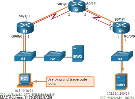 Usually what initiates a troubleshooting effort is the discovery that there is a problem with end-to-end connectivity. Two of the most common utilities used to verify a problem with end-to-end connectivity are ping and traceroute.
Step 1 – Verify the Physical Layer
 The show interfaces command is useful when troubleshooting performance- related issues and hardware is suspected to be at fault. Of interest in the output are the:
- Interface status
- Input queue drops
- Output queue drops
- Input errors
- Output errors
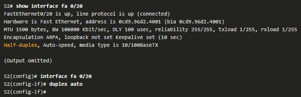
Step 2 – Check for Duplex Mismatches
The IEEE 802.3ab Gigabit Ethernet standard mandates the use of autonegotiation for speed and duplex and practically all Fast Ethernet NICs also use autonegotiation by default. Problems can occur when there is a duplex mismatch. 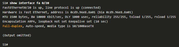
Step 3 – Verify Addressing on the Local Network
The arp Windows command displays and modifies entries in the ARP cache that are used to store IPv4 addresses and their resolved Ethernet physical (MAC) addresses. 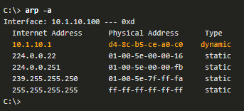
Troubleshoot VLAN Assignment Example
Another issue to consider when troubleshooting end-to-end connectivity is VLAN assignment.  For example, the MAC address on Fa0/1 should be in VLAN 10 instead of VLAN 1.
  The following configuration changes Fa0/1 to VLAN 10 and verifies the change.
Step 4 – Verify Default Gateway
Misconfigured or missing default gateways can cause connectivity problems. 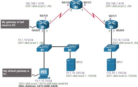 In the figure for example, the default gateways for:
- R1 is 192.168.1.2 (R2)
- PC1 is 10.1.10.1 (R1 G0/0/0)
Useful commands to verify the default gateway on:
- R1: show ip route
- PC1: route print (or netstat –r)
Troubleshoot IPv6 Default Gateway Example
An IPv6default gateway can be configured manually, using SLAAC, or by using DHCPv6.  For example, a PC is unable to acquire its IPv6 configuration using SLAAC. The command output is missing the all IPv6-router multicast group (FF02::2).
  R1 is enabled as an IPv6 router and now the output verifies that R1 is a member of ff02::2, the All-IPv6-Routers multicast group.
Step 5 – Verify Correct Path
When troubleshooting, it is often necessary to verify the path to the destination network. 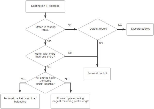
- The figure describes the process for both the IPv4 and IPv6 routing tables.
- The process of forwarding IPv4 and IPv6 packets is based on the longest bit match or longest prefix match.
- The routing table process will attempt to forward the packet using an entry in the routing table with the greatest number of leftmost matching bits.
- The number of matching bits is indicated by the prefix length of the route.
Step 6 – Verify the Transport Layer
Two of the most common issues that affect transport layer connectivity include ACL configurations and NAT configurations.
- A common tool for testing transport layer functionality is the Telnet utility.
- For example, the administrator attempts to Telnet to R2 using port 80.

Step 7 – Verify ACLs
On routers, there may be ACLs that prohibit protocols from passing through the interface in the inbound or outbound direction.  In this example, ACL 100 has been incorrectly configured inbound on the G0/0/0 instead of inbound on S0/1/1.
  The ACL is removed from G0/0/0 and configured inbound on S0/1/1.
Step 8 – Verify DNS
The DNS protocol controls the DNS, a distributed database with which you can map hostnames to IP addresses.
- When you configure DNS on the device, you can substitute the hostname for the IP address with all IP commands, such as ping or telnet. command output.
- Use the ip host global configuration command to enter a name to be used instead of the IPv4 address of the switch or router, as shown in the command output.


- Use the nslookup Windows command to display the name-to-IP-address mapping information.